Bleeding a tractor fuel system: Massey Ferguson and Ford
- Author
- Süleyman Kumru
- First published
- First published:
- Last updated
- Last updated:
- Reading time
- 6 min read
- Category
- Tractors
A tractor with a mechanical injection pump is bled from the tank towards the injectors: first the bleed screw on top of the filter, then the screws on the injection pump, last the pipe unions at the injectors. Where the screws are and the order of closing depend on the engine. The makers’ sequences follow for the three-cylinder Perkins in Massey Ferguson tractors and the Ford 2000, 3000, 4000 and 5000.
Short answer
- General rule: start at the bleed point nearest the tank, finish at the injectors. Close each when the fuel runs bubble-free.
- Massey Ferguson 240: two vent screws on the pump and the filter vent plug, bled with the lift pump lever and closed in the order filter, pump head, governor cover.
- Ford 2000 to 5000: filter screw, pump screw, injector unions. With a Simms pump, use the lift pump lever.
- Other tractors: follow the tractor’s own operator’s manual; do not borrow another engine’s sequence.
Why will a tractor not start with air in the fuel?
Air in the fuel system keeps the fuel from reaching the injectors. The Perkins workshop manual lists how it gets there:
“Air can enter the system as a result of running out of fuel, leaks in the system, changing filter elements or disturbance of fuel connections.”
Perkins Engines, Workshop Manual for 3.152 and D3.152 engines, 1982
Its fault-finding chart gives three causes for an engine that “starts and stops”: a choked fuel filter, a restriction in the air cleaner or induction system, and air in the fuel system. Common rail, and diesel bleeding in general, are a separate article.
In what order is the air bled out?
In the order the fuel flows. Perkins gives the route: pre-filter, lift pump, final filter, injection pump, injectors. A Utah State University Extension fact sheet has the same rule: one bleed screw at a time, “beginning closest to tank and ending at nozzles if necessary”. The two sequences below apply only to those engines. On other tractors, the Fiat 480 and 640 among them, follow the tractor’s own book: even these two do not agree. Only the direction stays the same: tank to injectors.
How do you bleed a Massey Ferguson 240 fuel system?
On a Massey Ferguson 240 the bleed points are two vent screws on the injection pump and, where fitted, the vent plug on the final filter. The engine is a three-cylinder Perkins AD3.152; the sequence is from Perkins’s workshop manual for the 3.152 series, which also covers engines built for Massey Ferguson. The pump is a C.A.V. DPA, “of the distributor type”; workshops call it a rotary pump.
- Governor cover. Slacken the air vent screw on the side of the pump’s governor control cover.
- Pump head. Slacken the vent screw on one of the two hydraulic head locking screws, on the side of the pump body.
- Filter. Slacken the vent plug on top of the final filter, where fitted.
- Lift pump lever. Work the priming lever. When bubble-free fuel comes from all three points, tighten in this order: filter, head locking screw, governor vent screw.
- Pump inlet. Slacken the pipe union at the pump inlet, work the lever, and retighten when bubble-free fuel shows round the threads.
- Injector pipes. Slacken the unions at the injector end of two of the high-pressure pipes. Throttle fully open, stop control at run.
- Turn the engine. When bubble-free fuel comes from both pipes, tighten the unions.
A drained thermostart (manifold heater) feed pipe must be bled at the thermostart before use. Massey Ferguson tractors with other engines have their own sequence.
What is the sequence on a Ford 3000 or 5000?
On the Ford 2000, 3000, 4000 and 5000 the order is filter screw, pump screw, injector unions. Ford’s operator’s handbook shows two pump layouts, C.A.V. and Simms.
- Tank. “Ensure that there is adequate fuel in the tank.”
- Filter. Loosen the bleed screw on top of the filter (both, if two) and retighten when the fuel runs bubble-free. With a Simms pump, work the lift pump priming lever.
- Injection pump. Do the same at the pump’s bleed screw.
- Injectors. Loosen the pipes at the injectors, turn the engine until bubble-free fuel flows from each connection, then retighten.
The handbook mentions the lever only for the Simms pump, and its drawings show one only in that layout. On the other, the fuel presumably reaches the screw under its own weight. The handbook does not say so; that is our reading. Vintage Tractor Engineer, a site about older tractors, notes that a tank above the engine “gives the aid of gravity”.
How many injector unions are slackened, and when are they tightened?
The sources differ on how many unions to slacken: Perkins says two of the three pipes, Ford all of them. Those two are the manufacturer instructions.
| Source | Slackened | Tightened |
|---|---|---|
| Perkins 3.152 workshop manual | Two of the three pipes | When both run bubble-free |
| Ford 2000–5000 operator’s handbook | All the pipes | When each connection runs bubble-free |
| Utah State University fact sheet | Half the lines, about one turn | One by one, once the engine fires |
After an injector change Ford finishes on the starter: stop control pushed in, the engine is cranked until air-free fuel comes from the loose connections, and each is tightened in turn during cranking. The fact sheet asks for two wrenches on the union, to “prevent the binding or twisting of the steel lines”.
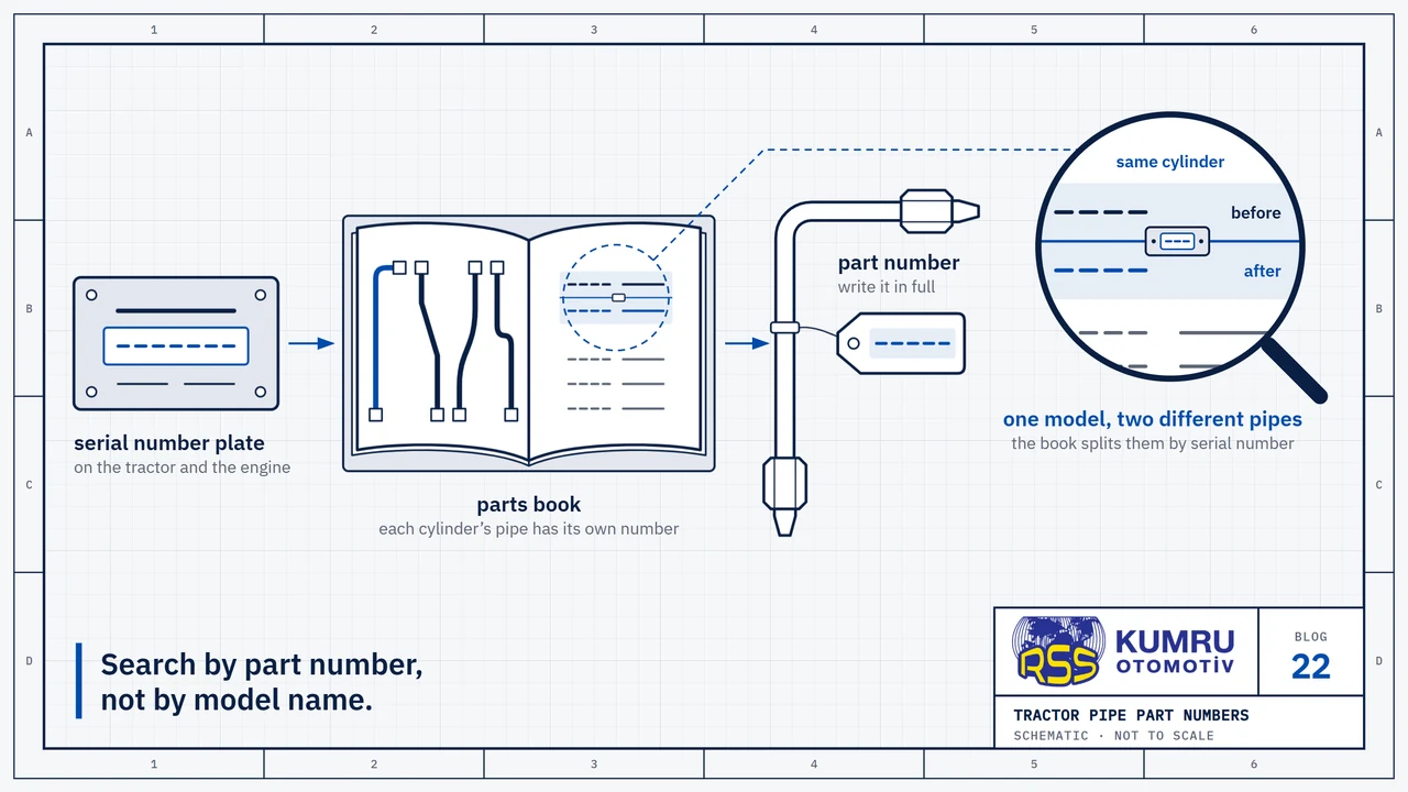
Perkins gives 20 Nm (15 lbf ft) for the high-pressure pipe unions on this engine, with a warning: “If the union is tightened excessively, the nipple may be damaged.” The nipple is the sealing end of the pipe; once damaged it leaks, and the complete pipe is replaced. Finding the right pipe by part number is covered in the Massey Ferguson and Ford pipe article.
The figure is for this engine only; other tractors take the torque in their own service data. A union closed during cranking gets its final torque once the engine has stopped. Neither book says so; that is our reading.
Keep your hands out of the fuel coming from a slackened union. Perkins puts the working pressure of these joints at “several thousand pounds per square inch”, and Vintage Tractor Engineer warns that the fuel can enter the skin. Closing a union during cranking, or as the engine begins to fire, is for mechanical pumps only; on common rail the unions are not slackened to bleed the system.
Lift pump will not prime, or the air keeps coming back?
Start with the tank and its tap, then the lift pump. If the lever cannot be pushed down, Perkins says to rotate the engine one complete revolution: the eccentric on the camshaft is at its maximum lift. The manual’s test: with the outlet pipe off, fuel should spurt at every stroke of the lever.
If the air keeps coming, Vintage Tractor Engineer lists possible causes:
- blocked pipes or filters
- an inoperative lift pump
- frozen or waxed fuel
- split suction pipes letting air in
- a damaged injection pump or a sheared pump drive
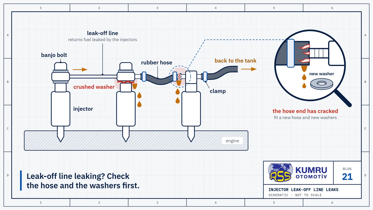
Perkins adds the glass-bowl pre-filter: after cleaning, its joints must be sound, “as any leakage of air here may cause air locks in the fuel system.” Check in flow order: tank, suction pipes, pre-filter, lift pump, final filter. The injection pump and injectors come last; the Utah fact sheet wants them left alone. The injector leak-off hose is covered in the tractor leak-off hose article.
Sources
- Perkins Engines, “Workshop Manual for 3.152 & D3.152 Diesel Engines (Publication No. 601SER06821031)”, engine maker's workshop manual, 1982; OCR text of the scan on the Internet Archive.
- Ford Motor Company, “Tractor Operations: Operators Handbook, Ford 2000, 3000, 4000 and 5000 (SE 3112)”, operator's handbook, section G; print date illegible on the cover; OCR text of the scan on the Internet Archive.
- Utah State University Extension, “Bleeding Air From Diesel Fuel Lines and Filters”, peer-reviewed fact sheet by Dr. Von H. Jarrett, undated.
- Vintage Tractor Engineer, “Bleeding Off Diesel Fuel Systems”, specialist site on vintage tractor maintenance, 14 January 2009.
- TractorData.com, “Massey Ferguson 240: Engine”, tractor reference database, page updated 5 September 2025; used only for the engine type.
Sources were checked again on October 8, 2026.
RSS Kumru Automotive
RSS Kumru Automotive was founded in 1990 and specialises in hydraulic systems and fluid management. Our range includes more than 300 pipe references for Massey Ferguson and Ford tractors.
Brand names and OEM reference numbers are used for identification and compatibility information only.