Massey Ferguson 135 / 240 hydraulic lift not working: standpipe, O-rings and the order of checks
- Author
- Süleyman Kumru
- First published
- First published:
- Last updated
- Last updated:
- Reading time
- 6 min read
- Category
- Tractors
When the rear lift on a Massey Ferguson 135 or 240 will not raise, raises slowly or will not hold a load, start with what needs no spanner: the quadrant levers, the oil level and the implement. Next come the standpipe, which carries oil from the pump up to the lift cylinder, and its O-rings; the pump, control valve and relief valve come last.
Short answer
- Outside first: in position control the draft lever sits at the top; the oil is read on the right-hand dipstick; a clutch pedal held to the floor stops the pump.
- Then the standpipe: take off the small cap under the seat, pull the pipe, check its O-rings and back-up washers.
- Read the symptom: a lift that works cold and fails hot is losing oil inside.
- Last: control valve, relief valve and pump; the top cover comes off for those.
Massey Ferguson 135 hydraulic lift problems: what do you check before taking anything apart?
The levers, the oil, the clutch and the implement. Massey-Ferguson’s workshop manual ends its trouble-shooting table with a note: some apparent hydraulic faults come from “failure to operate the system as it was designed to be operated”, others from maladjusted or badly worn implements.
The French operator’s book for the 135 describes three levers: position, draft and response. In position control the draft lever is parked at the top of its quadrant and the implement is raised by moving the position lever to “Transport”. Pulled to the rear, the book says, the response lever makes the implement rise and lower more slowly.
- Oil: the lift shares its oil with the gearbox and rear axle. The dipstick is on the right of the rear axle housing; the book has the level checked every 100 hours.
- Clutch: on the dual clutch, the first part of the pedal travel frees only the transmission. Pressed to the floor, the pedal stops the hydraulic pump too.
- Implement: lifted by hand and let go, the lower links “should fall of their own weight”. A load beyond what the system can handle opens the relief valve, and the operator’s book warns that this can, in the long run, bring the pressure down.
Where is the standpipe and what does it do?
“The stand pipe takes oil from the pump and up into the lift cylinder,” writes Vintage Tractor Engineer, a site on older tractors, about the MF 35. It sits below a small cap under the front right-hand side of the seat and pulls out once the cap is off.
Massey-Ferguson’s workshop manual for the MF 35, 50 and 65 calls that cap the transfer plate and counts three O-rings: one “on each end of the standpipe” and one in the plate. Vintage Tractor Engineer adds a back-up washer beside the O-ring and calls these O-rings “a common place for oil to leak”. Its advice to an MF 35 owner with a slow lift: “The next (easiest and least expensive) thing to check would be the o’rings on the stand pipe.”
Is the lift on a Massey Ferguson 240 checked the same way?
On the two sources we have, yes. Writing in 2020 about an MF 230, Vintage Tractor Engineer notes that “the top cover is very similar on the MF35, 100 series, 200 series, 300 series, 500 series and even the TE20 tractors”. On a tractor forum in 2023, an MF 240 owner whose pump gave no pressure was told the standpipe could be checked first: its O-rings sometimes blow, and broken standpipes have been seen. The same reply has the screen behind the bottom cover pulled out and washed.
We could not open Massey Ferguson’s own workshop manual for the 135 or the 240. The trouble-shooting table used below is from the MF 35, 50 and 65 manual; carrying it over to these two models is our inference from that likeness.
What if the lift works cold but not hot, or lifts in jerks?
A lift that works cold and fades as the oil warms up is losing oil inside. Warm oil, Vintage Tractor Engineer explains, is thin enough to get past a worn part: “if it gets worse as the oil warms up then the hydraulic fluid is leaking somewhere”. It names a slightly damaged O-ring on the standpipe, the rings on the lift cylinder and general wear in the pump.
For a jerky, uneven lift the manual’s table blames the pump: “One or more inoperative side chamber valves”. The pump comes out and the valve seats are checked for dirt. On a forum, an MF 135 that raised “shaky” at idle drew a similar first guess: a worn pump or its control valves.
The 135 operator’s book also has the suction strainer cleaned, and the oil changed, every 800 hours; it is reached through the right-hand plate that carries the dipstick.
Where do you look when the lift will not hold a load?
Through the inspection cover on the right-hand side, with the system working. Under “Implement will not raise”, the manual’s entry for a leak names four places:
“Remove inspection cover and check system while operating. Check for leaks at the ram cylinder, standpipe, control valve, and pump side chambers.”
Massey-Ferguson, MF 35, 50 and 65 workshop manual, hydraulic system trouble shooting
The table has no row for a lift that sinks under load; tying the leak entry to that symptom is our inference. A forum reply to an MF 135 owner whose lift “won’t hold the attachment up when the tractor is shut off” names the same places: stand pipe connections, lift cylinder, pump control valve. It suggests watching through the inspection port for “a stream or drip”, with a mechanic’s mirror to help.
What matters when the standpipe O-rings are renewed?
Keep your hands out of the housing while the engine is running. Vintage Tractor Engineer writes that warning in capitals. The 135 operator’s book has the relief valve opening at 175 kg/cm²; the MF 35, 50 and 65 manual describes a 2,500 p.s.i. system. Why a pressure leak is never felt for by hand is in our article on hydraulic injection injuries.
- Arms down. The manual wants the lift arms “all of the way down” before the transfer plate comes off.
- No lever under the plate. If it is tight, turn it while lifting.
- Three O-rings. The two on the pipe and the one in the plate must be in place and “either new or serviceable”; fit the back-up washers too.
- Cleanliness. The manual’s caution: keep dirt and grit out of the hydraulic system.
- Try it. Raise and lower the implement several times; the manual does this to drive out trapped air.
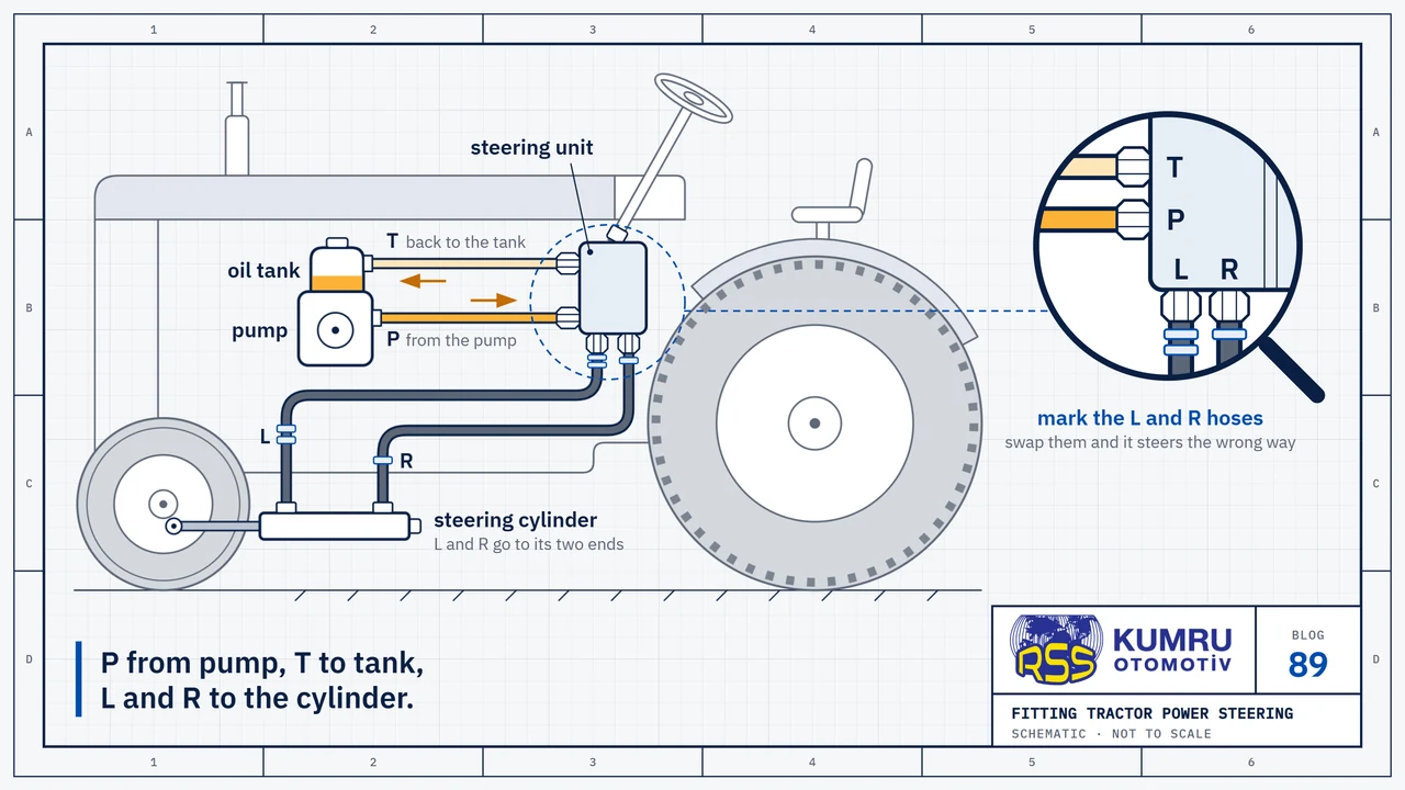
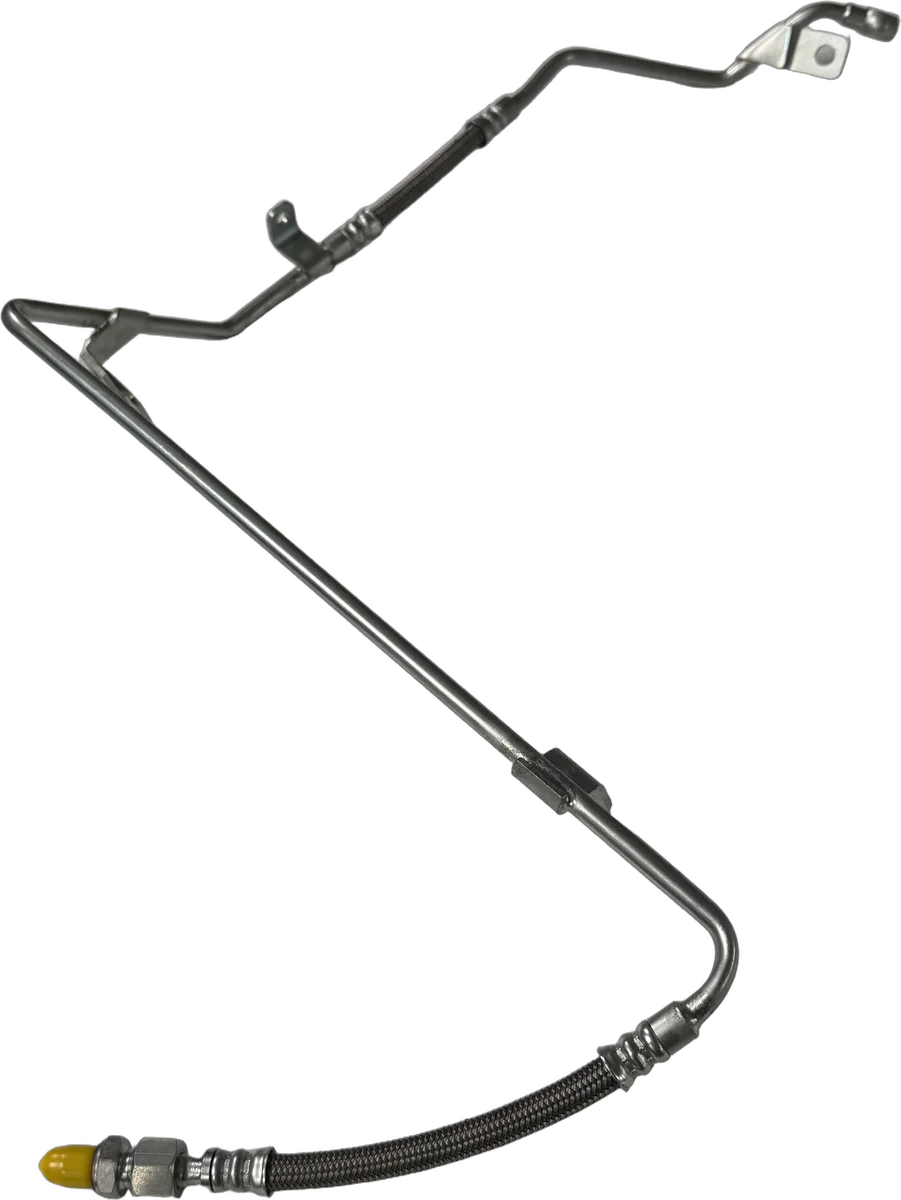
Cap screw torque is in the tractor’s own manual. A broken pipe is ordered by part number, not by model name. Leaks in power steering pipes and hoses have an article of their own.
In what order does a mechanic check?
- Levers and clutch. Draft lever at the top? Response lever left at the rear? Foot off the clutch?
- Oil. Is the level right on the dipstick?
- Implement. Do the lower links fall of their own weight? Is the load too heavy for the system?
- Standpipe. Take off the cap, pull the pipe, renew the O-rings and back-up washers.
- Inspection cover. Look for the leak from the right with the system working, hands outside.
- Pump side. Control valve, relief valve, pump. Broken pump parts, the table says, “Will probably be indicated by a noisy pump.”
Sources
- Massey-Ferguson, “MF 65 Tractor Workshop Service Manual (Publication No. 1448 812 M1), Group III, Section A, Part 1: Internal Hydraulic System, MF & TO 35, 50, and 65 Tractor”, maker's workshop manual, internal hydraulic system part (MF 35, 50 and 65); trouble-shooting table, removing and installing the lift cover; print date not legible in the text; OCR text of the scan on the Internet Archive, quotations read from the page images.
- Massey Ferguson (Éditions Techniques Massey-Ferguson S.A.), “Tracteurs 133 - 135 super, 135 - 140 super, 148: Livret d'utilisation et d'entretien (1.646.062 M1)”, maker's operator's and maintenance book, in French; print code ET 5673-5-73 (May 1973); hydraulic levers, clutch, oil level, suction strainer, relief valve pressure; OCR text of the scan on the Internet Archive, figures read from the page images.
- Vintage Tractor Engineer, “MF35 Slow Hydraulic Lift”, specialist site on vintage tractor maintenance, 2 January 2010; the site's last reply in the comments is dated 25 March 2013; not a manufacturer instruction.
- Vintage Tractor Engineer, “Massey Ferguson 35 Hydraulics Won't Lift”, specialist site on vintage tractor maintenance, 14 January 2009; the site's reply in the comments is dated 15 October 2012; not a manufacturer instruction.
- Vintage Tractor Engineer, “MF 230 Sleeve Fitted To Top Cover”, specialist site on vintage tractor maintenance, 24 November 2020; used for the likeness of the top cover across the MF 35, 100 series and 200 series; not a manufacturer instruction.
- TractorByNet, “Massey 240 problem- hydraulic lift not working”, forum thread, 31 October to 10 November 2023; a question from a Massey Ferguson 240 owner and one reply; used as a field account, not a manufacturer instruction.
- TractorByNet, “Massey 135. 3-point lift issue”, forum thread, 11 February to 1 March 2019; a question from a Massey Ferguson 135 owner and the replies; used as a field account, not a manufacturer instruction.
Sources were checked again on October 13, 2026.
RSS Kumru Automotive
RSS Kumru Automotive was founded in 1990 and specialises in hydraulic systems and fluid management. Our range includes more than 300 pipe references for Massey Ferguson and Ford tractors.
Brand names and OEM reference numbers are used for identification and compatibility information only.