Cat 3208 and 3304 fuel lines: which line goes where, and how a 3304/3306 is bled
- Author
- Furkan Kumru
- First published
- First published:
- Last updated
- Last updated:
- Reading time
- 6 min read
- Category
- Caterpillar
On the Cat 3208 and 3304, fuel reaches the injection pump housing at low pressure through a filter and the fuel transfer pump. One high-pressure line runs from the housing to each cylinder, and a return line takes part of the fuel back to the tank. Caterpillar’s 3304/3306 industrial engine guide covers filters and bleeding for both engines. The route below is taken from those books.
Short answer
- Low-pressure side: tank, filter, transfer pump, injection pump housing.
- High-pressure side: one pump element and one line per cylinder. On the 3208 the line ends at an adapter in the head.
- Return line: a constant bleed valve sends fuel and air back to the tank.
- Removal: tag the lines, cap the ends, tighten to the book figure, refit clamps and dampers.
In what order does fuel get from the tank to the pump?
The filter sits ahead of the transfer pump on the 3208, and on both sides of it on the 130G grader’s 3304. In Caterpillar’s service manual for the 3208 truck engine (serial 2Z1 and up) the pump pulls fuel from the tank through the water separator, if fitted, and the fuel filter. Fuel enters the injection pump housing at the top and goes through an inside passage to the transfer pump on the front, which fills the housing under pressure. A bypass valve controls it: 205 ± 35 kPa (30 ± 5 psi) at full load.
For the 3304 we read the US Army’s maintenance manual for the Caterpillar 130G grader (engine: 3304DIT), by its own note an authentication of the manufacturer’s commercial literature. There fuel passes the primary fuel filter and check valves to the transfer pump, which pushes it through the secondary fuel filter to the fuel manifold in the housing, at 170 to 280 kPa (25 to 40 psi).
The 3304/3306 guide also names two filters: a primary filter that is washed and a final filter that is replaced. We could not open a Caterpillar systems manual giving the flow for the 3306; on that engine the route is confirmed in the machine’s own service manual.
| Line | From and to | Pressure | Book |
|---|---|---|---|
| Supply line | Tank, water separator (if fitted), filter, pump housing, transfer pump | Low; suction side | 3208 |
| Supply line | Tank, primary filter, transfer pump, secondary filter, fuel manifold in the housing | Low; 170 to 280 kPa | 3304 (130G) |
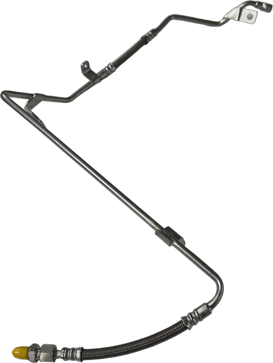
| Fuel injection lines | Pump element in the housing to that cylinder’s nozzle; on the 3208, to the adapter in the head | High | 3208, 3304 |
| Constant bleed (return) line | Constant bleed valve to tank; on the 3208, from the pump housing | Low | 3208, 3304 |
3208 rows: truck engine service manual; 3304 rows: 130G manual. The sections read do not say whether low-pressure lines are hoses or tubes.
On the 3208 the tank lines meet the engine at a fuel junction block at the right rear: supply connections for tank and filter, constant bleed connections for tank and pump housing.
Where do the high-pressure lines run?
Each line runs from one pump element in the housing to the nozzle of the same cylinder. The 130G manual: “There is one fuel injection pump for each cylinder in the engine.” The pump pushes fuel at very high pressure through the line to the nozzle.
On the 3208 the line does not reach the nozzle directly. The nozzle sits under the valve cover; line and nozzle both connect to an adapter in the cylinder head, and the service manual fits new O-ring seals to adapter and nozzle on assembly. Tracing a leak at such a pass-through, on another Cat engine, is covered in a separate article.
The lines are not interchangeable: “Each fuel injection line of an engine has a special design and must be installed in a certain location.” The 3208 operation manual adds that on some later engines the line is routed over the rocker arm assembly, has a larger inside diameter and carries notched nuts; there line and nozzle come out as an assembly.
What is the return line for?
The return line carries a steady share of the fuel back to the tank, which removes air and keeps the system cool. In both books a constant bleed valve does this. In the 130G manual it returns approximately 34 liters (9 gal.) per hour of fuel and air: “This helps keep the fuel cool and free of air.” The 3208 manual also gives approximately 9 gallons per hour: the flow removes air from the pump housing, and a check valve restricts it until housing pressure reaches 55 ± 20 kPa (8 ± 3 psi).
What does the book ask for when a line comes off?
The sequence in the 3208 service manual:
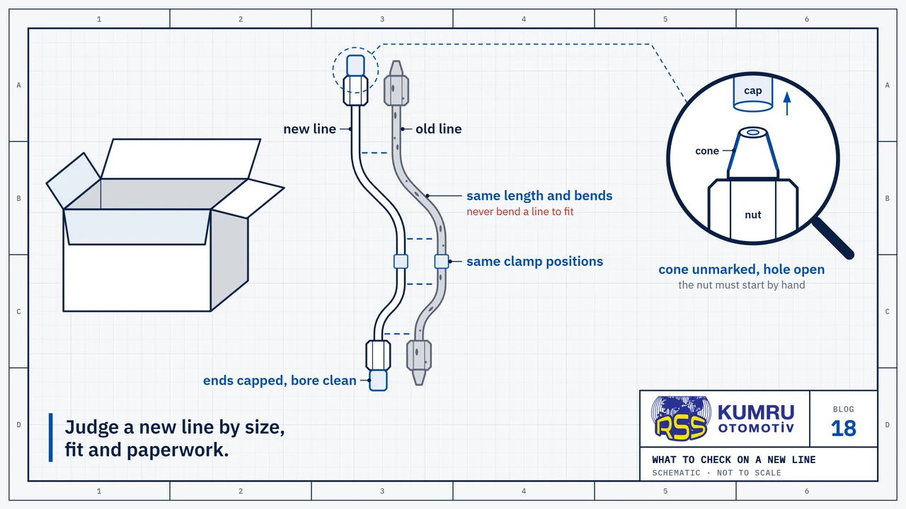
- Mark the lines. Marks or tags go on as lines are removed, so each returns to its place.
- Loosen the nuts at both ends. The bracket bolt comes out; nuts are loosened at the cylinder head and the injection pump.
- Close every opening. Caps or plugs keep dirt out.
- Tighten to torque. The disassembly and assembly section gives 40 ± 7 N·m (30 ± 5 lb ft).
- Refit clamps and dampers in their original location. The bracket bolt goes in last.
The testing and adjusting section of the same manual prints 42 ± 7 N·m (31 ± 5 lb ft); the specifications section and the operation manual give 40 ± 7 N·m. The reason given: a loose nut leaks, and “If the nut is tightened too tight, the inside diameter of the line will become smaller and cause a restriction to the flow of fuel in the line.” These values are for the 3208; a 3304 or 3306 takes the torque in its own service manual.
The 3208 service manual warns: “Do not check for pressure leaks with your hand. High pressure oil or fuel can pierce the skin.” And: “Never bend a fuel injection line, or install a line which has been bent.” Lines stay clear of other components and hot parts.
In what order is the system bled?
Bleeding starts at the vent valve on the pump housing; the lines are opened only if the engine still runs badly. In the 3304/3306 guide the governor control goes to the OFF position, the vent valve is opened and the priming pump is operated until the flow of fuel is continuous and free of air bubbles. The valve is closed, the pump locked and the engine started. If it still misfires or smokes:
“With the engine running, loosen the fuel lines at the cylinder head, one at a time, and allow the fuel to run until free of air bubbles.”
Caterpillar, Operation & Maintenance, 3304/3306 Industrial Engines
The 3208 operation manual has the nuts loosened at the cylinder head and the engine cranked until fuel flows free of air bubbles; the testing section of the service manual adds 1/2 turn and the low idle position. The troubleshooting section starts the engine, then loosens the nuts one at a time. Neither operation manual wants a new filter filled with fuel before fitting. Bleeding on other fuel systems is covered in a separate article.
What order should the work follow?
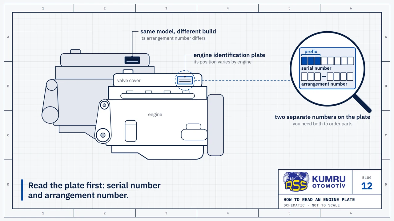
- Identify the engine and the book. The serial and arrangement numbers lead to the right manual; where to find them is explained in a separate article.
- Mark, cap, do not bend.
- Tighten to the book torque, then refit the clamps.
- Bleed at the pump housing first, then at the lines if needed.
Sources
- Caterpillar, “3208 Diesel Truck Engine Service Manual, Form No. SEBR0541-03 (2Z1-UP)”, service manual, full-text copy on the Internet Archive; the copy read carries no print date; safety pp. 10–11, systems operation pp. 2-2 to 2-10, testing and adjusting p. 3-2, disassembly and assembly pp. 6-28 and 6-72.
- Caterpillar, “3208 Truck Engine Operation and Maintenance, SEBU5947-07”, operation and maintenance manual, full-text copy on the Internet Archive; the copy read carries no print date; pp. 33 and 49–51.
- Caterpillar, “Operation & Maintenance: 3304/3306 Industrial Engines, SEBU5779”, operation and maintenance guide, full-text copy on the Internet Archive; the copy read carries no print date; pp. 10 and 35–36.
- U.S. Department of the Army, “TM 5-3805-263-14&P-2: Unit, Direct and General Support Maintenance Manual for Grader, Heavy, Road, Motorized”, maintenance manual for the Caterpillar 130G grader (engine: 3304DIT), 14 April 1989; by its own note an authentication of the manufacturer's commercial literature; the copy read is the opening part of the book, pp. 1-6 to 1-8.
Sources were checked again on October 9, 2026.
RSS Kumru Automotive
RSS Kumru Automotive was founded in 1990 and specialises in hydraulic systems and fluid management. Our range includes more than 1,000 pipe and hose references for Caterpillar engines and machines.
Brand names and OEM reference numbers are used for identification and compatibility information only.