Cat 3406B and 3406C injector line leaking at the head: O-ring, inner line and bleeding
- Author
- Furkan Kumru
- First published
- First published:
- Last updated
- Last updated:
- Reading time
- 6 min read
- Category
- Caterpillar
On a Cat 3406B or 3406C the injector line does not reach the injector from outside. The nozzle sits under the valve cover: the line from the pump ends at an adapter through the head, and a short inner line runs on to the nozzle. So fuel at the edge of the head is not always from the outer nut. Find where it starts before touching the nut, the O-ring or the line.
Short answer
- Layout: outer line, adapter through the head, inner line under the valve cover, with an O-ring at its adapter end.
- Leak: fuel behind the outer nut points to the cone seat. Dry nut, wet adapter: the valve cover comes off.
- Oil: a leak under the cover does not show outside and can put fuel in the oil.
- Bleeding: Caterpillar’s 3406C manual loosens the line nuts at the valve cover base, one at a time.
How does the injector line get through the head?
On the 3406B and 3406C the injector line passes through the head by way of an adapter. A 1983 Caterpillar patent gives the reason:
“In engines that have fuel injectors that are located inside of the valve covers, the high pressure fuel lines to the injectors must pass through either a wall of the engine or the valve cover.”
Caterpillar Tractor Co., US Patent 4,384,557, 24 May 1983
The fitting in that wall has two jobs, the patent says: to keep the lubricating oil in and to keep diesel fuel out of it. A 1984 Caterpillar patent describes the arrangement usual until then: a long adapter between outer and inner line, with a cone seat and a nut at each end. That makes two joints at the wall.
In a nozzle-removal video on the Adept Ape channel, the outer line of a 3406B “runs to an adapter through the head”, and a short jumper line joins adapter and nozzle. The jumper has “an o-ring on one side that you’ll want to replace”; the other end is “just a compression fit”.
Where does fuel at the head come from, and how is it told from a nut leak?
Fuel at the edge of the head comes from one of the two joints at the adapter, and only a look at the engine tells which. The adapter in the 1983 patent has a drain passage, so fuel seeping past a cone goes outside, not into the oil. Of earlier designs it says: “Any internal leakage within the fitting flows through the drain passage, out to the atmosphere, and down the side of the engine.”
It adds that fuel running down the inlet line could “mislead the operator into believing that the leakage is from the fuel injection pump”. None of the documents we could open says whether the 3406B or 3406C adapter has such a drain; the parts book will show it.
So wash and dry the area, run the engine and watch where fuel first appears. Fuel from behind the outer nut means the outer cone is not sealing; that joint is covered in a separate article. A dry nut and a wet adapter point under the cover. That step is our own reading of the patent, which has the valve cover removed once fuel shows at the drain.
Will a new O-ring stop the leak?
A new O-ring will not stop a leak that is at the cone. In the patent’s fitting the cone holds the pressure: the nut draws the conical end onto its seat and the seal is made there. The O-ring is a second line; it keeps fuel that has passed the cone from escaping around the nut. At the inner end, that sends the fuel to the drain and not into the oil.
The patent’s remedy is to tighten the nuts or replace the line; the service manual torque sets the limit. The technician in the video fits a new O-ring whenever the inner line is off, and refits the line unless it is damaged or bent. Refitting a sound line has limits, covered in a separate article.
Can the fuel get into the oil?
Fuel can reach the engine oil when the leaking joint is the one under the valve cover, and nothing shows outside. On a heavy-equipment forum, a senior member told a 3306 owner with fuel in the oil that such a leak is not so obvious “when connections are buried under the valve cover”. That owner’s injectors turned out not to be under the cover.
Adept Ape’s fuel dilution video shows a method: dye in the fuel filter, a short run, valve cover off, black light. On older mechanical engines, the technician says, fuel enters the oil at the nozzles, the lines leading to them, or the high-pressure pump. Thinned oil is changed with its filter, because it can damage bearings.
How is the inner line taken off and refitted in the field?
Caterpillar’s 3406C Operation and Maintenance Manual leaves nozzle removal to the Service Manual. This is the order the technician in the video shows on a 3406B; torque figures come from the service manual.
- Covers off. The valve cover over that cylinder, the engine-brake housing if fitted, and the valve cover base.
- Loosen the nut at the adapter first, then the nut at the nozzle. The outer line stays on.
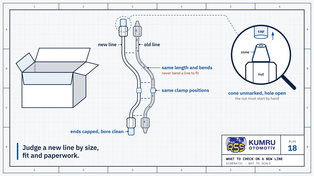
- Inspect the line for damage and bends. Renew the O-ring every time.
- Fit the O-ring end first. Oil the O-ring, push that end into the adapter, run both nuts down by hand.
- Torque the nozzle nut first, then tighten the nut at the adapter.
Two notices from the manual apply. One: “Do not let the tops of fuel nozzles turn when the fuel line nuts are loosened or tightened.” The other: “Do not bend or strike high pressure lines. Do not install bent or damaged lines, tubes or hoses.”
How is the system bled after the lines have been off?
Caterpillar’s 3406C industrial engine manual writes its priming procedure for a dry system and for filter changes. Start at the priming pump: unlock it and pump until resistance is felt. Open the vent valve on the injection pump housing, if fitted, and pump until the fuel runs free of bubbles. If the engine still will not start or runs rough, go to the lines:
- Loosen the fuel line nuts at the valve cover base. The manual: “Loosen these line nuts one at a time.”
- Work the priming pump until fuel flows from the line without bubbles. Without a priming pump, crank the engine.
- “Tighten each fuel line nut before you loosen the next fuel line nut.” The manual gives 40 ± 7 N·m (30 ± 5 lb ft).
That figure is for the 3406C; we could not open a Caterpillar document for the 3406B, so use its own service manual. Bleeding other fuel systems is covered in a separate article.
Caterpillar’s warning: “Fuel leaked or spilled onto hot surfaces or electrical components can cause a fire.” Hold a cloth around the nut you loosen and wipe up spills at once.
What order should the work follow?
- Find the source. Wash, dry, run, watch where fuel first appears.
- Outer nut wet: check the torque once against the service manual. Still leaking: look at the cone.
- Adapter wet or oil level rising: valve cover off, check the inner joints, fit a new O-ring.
- Bleed, run, look again. Fuel in the oil: change oil and filter.
Sources
- Caterpillar, “3406C Industrial Engines: Maintenance Intervals (excerpted from Operation & Maintenance Manual SEBU6993-02)”, excerpt from the Operation and Maintenance Manual, published by Caterpillar on safety.cat.com, 2007; that address no longer opens, so the copy on archive.org.
- Caterpillar Tractor Co., “US Patent 4,384,557: Apparatus for draining liquid from an engine”, US patent, 24 May 1983; describes a design and names no engine model.
- Caterpillar Tractor Co., “US Patent 4,445,713: Bulkhead-fluid-line connector”, US patent, 1 May 1984; used for its account of the adapter arrangement that was usual until then.
- Adept Ape, “How To Remove And Install 3406B Fuel Nozzles. 3406C Fuel Nozzle R & I.”, workshop video, 16 May 2018; read from YouTube's automatic captions; a field account, not a manufacturer document.
- Adept Ape, “How To Troubleshoot Fuel In Oil Contamination. Diesel Fuel Dilution.”, workshop video, 5 May 2016; the engine shown is a Cat C7; read from the captions; a field account, not a manufacturer document.
- Heavy Equipment Forums, “3306 fuel in oil problem PLEASE HELP”, forum thread, 21 May – 30 June 2022; a field account, not a manufacturer document.
Sources were checked again on October 8, 2026.
RSS Kumru Automotive
RSS Kumru Automotive was founded in 1990 and specialises in hydraulic systems and fluid management. Our range includes more than 1,000 pipe and hose references for Caterpillar engines and machines.
Brand names and OEM reference numbers are used for identification and compatibility information only.